Soviet Oscilloscope C1-94 Restoration
A few months ago, a lonely oscilloscope got into my possession. It was sort-of working, but it was a little dirty. The main BNC connector was loose, the time-base control was wobbly, and it was out of sync and not calibrated. I got this oscilloscope from my friend Ron (OM1ARH) for a symbolic price of 20€ + Kofola (a Slovak soft drink). I wanted an oscilloscope to play around with circuits that require one.
Cleaning and Disassembly
First things first: I needed to clean it up. For that, I had to remove the front panel controls, which turned out to be a little more difficult than I expected.
The tiny potentiometers were easy to remove—just a single flat-tip screw, and they were out. However, the larger time-base and amplifier controls were challenging because I didn’t initially see any screws. After some investigation, I realized the top plastic was glued onto the actual metal potentiometer. By carefully removing the decorative plastic, I accessed the two screws holding the metal piece. I repeated the process for the other potentiometer, unscrewed the bottom screw holding the front panel, and gently removed it.
With the front panel off, I cleaned it nicely with 99% alcohol.
Tackling the Electronics
When I disassembled the oscilloscope, I was shocked—not literally—to find all that Soviet engineering crammed in there so neatly. (I especially loved the delay loop cable!)
After admiring the design, I quickly dusted off the internals with compressed air and cleaned some potentiometers. I also tightened the main BNC connector, as its nut was loose.
Calibration and Testing
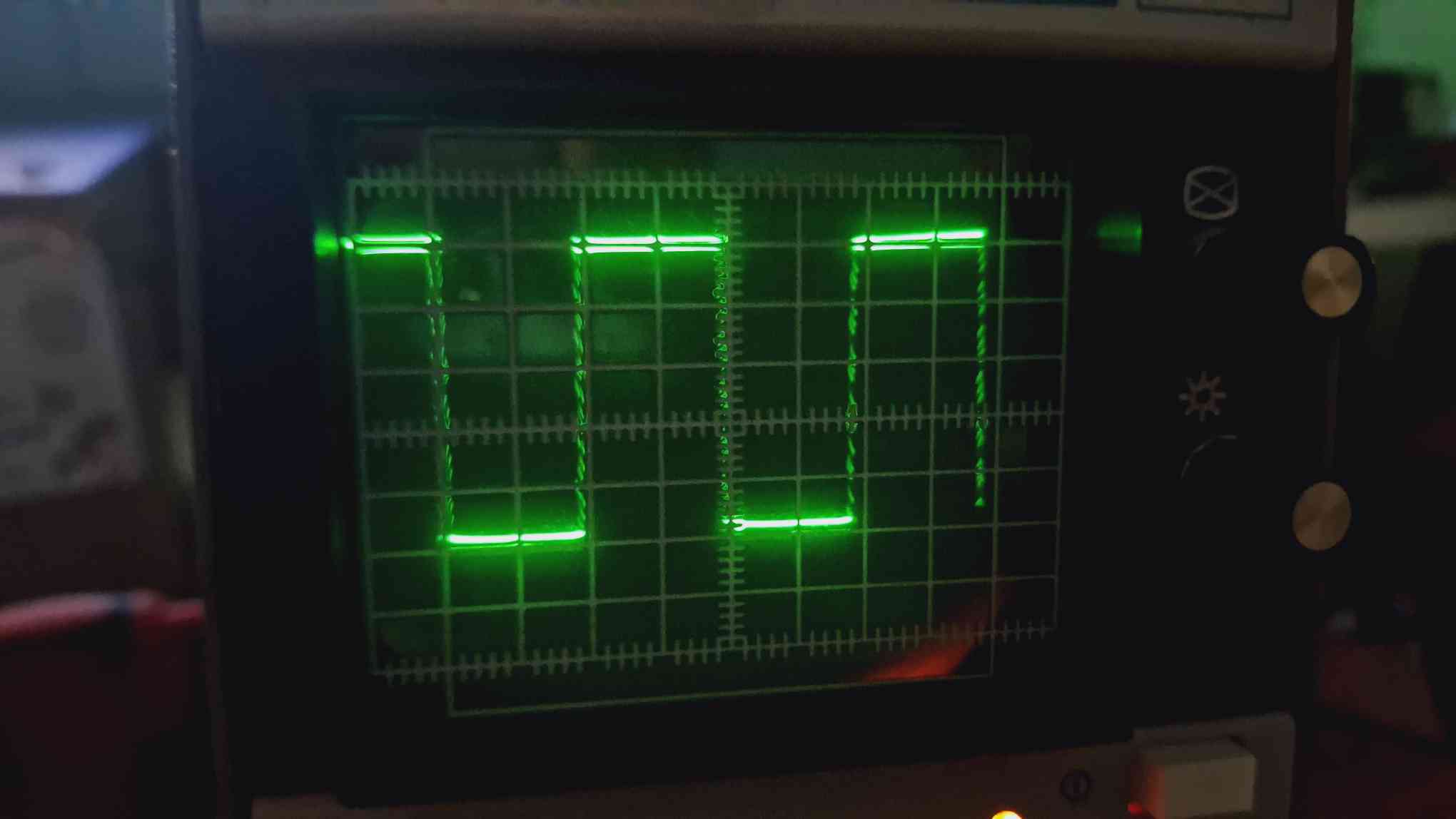
Reassembling the oscilloscope was straightforward, so I moved on to calibrating it. Using a reference picture I found online, I adjusted the unit based on the default square-wave signal present on the oscilloscope’s front panel. I tweaked the potentiometers until the signal lined up nicely.
Functionality Testing
To test the functionality:
- I used my DIY ARDF (foxhunt) transmitter for 80m, which emits beeps at around 3.5 MHz. The oscilloscope measured the frequency accurately.
- I tested the X/Y mode using oscilloscope art from YouTube (Link 1, Link 2). It worked beautifully!
The CRT has a very retro green coating. At lower brightness levels, it’s precise, but at higher brightness, the beam gets a bit thick for exact measurements. I also appreciated that the front grid is securely locked in place, preventing calibration issues from accidental bumps.
Final Thoughts
So, what’s my final conclusion? IT WORKS, AND I LOVE IT! 😃

